Myon-Shield
The \(400\,\text{GeV}\) SPS proton beam dump, delivering \(4 \cdot 10^{13}\) Protons during a one second spill on the target, will bombard the Hidden Sector Decay Spectrometer with approximately \(10^{11}\) muons per second1. Those muons are mainly originating from the decay of pions, kaons and charmed mesons within the beam-dump experiment.
Unlike hadrons, muons are highly penetrating and low ionizing particles, only interacting electromagnetically. They can travel through the shielding with only a small energy deposit and reach the decay vessel of the HSDS. Any detected hidden sector signal could be mimicked by a muon interacting with the detector material and producing a secondary particle, which could be misidentified as a hidden sector particle signal. A passive absorber, capable of stopping the highest-energy muons, would require a length of \(\gt 100\,\text{m}\) of shielding material, which is impracticable for the experiment. Since SHiP aims for a "Zero Background" environment, a shielding from these muons is needed to reduce the number of muons by at least four orders of magnitude1.
Fig. 1 shows the transverse momentum versus momentum distribution of the muons from the beam dump, simulated with Pythia8. The muons have a wide energy spectrum with momentum of up to \(350\,\text{GeV}\) and occupy a wide phase space.

Fig. 1: Transverse momentum versus momentum distribution2 of the muons from the beam dump, simulated with Pythia8.
Why not use a simple dipole magnet?
A simple and naive approach would be to use a simple dipole magnet to deflect the muons away from the detector. In the right configuration it can deflect the \(\mu^+\) to the left and \(\mu^-\) to the right. However, this would introduce multiple problems.
- 1. Magnetic Field strength:
-
The muons have a wide energy spectrum with an momentum of up to \(350\,\text{GeV}\). The deflection angle \(\theta\) of a particle with charge \(q\) and momentum \(p\) in a magnetic field \(B\) is given by:
- A single dipole magnet would either have to be very long or have a very strong magnetic field to deflect the high energy muons.
- 2. Muon Phase Space:
-
The muons from the beam dump cover a wide section of the phase space. They have different energies, angles and starting positions. Therefore, a single dipole magnet could deflect two muons, originally travelling away from each other, into the detector acceptance. This is visualized in Fig. 2.
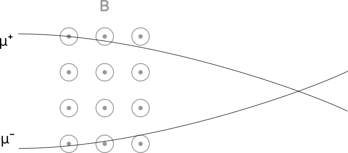
Fig. 2: A schematic, simplified visualization of the deflection problem of a single dipole magnet. The muons have different starting positions and angles, which can lead to a collision after deflection by the dipole magnet.
- 3. Return Field:
-
Since magnetic field lines must close, every dipole magnet has a return fields. Muons that are already moving away from the detector may traverse these regions of opposite magnetic field and get deflected back into the detector. This is visualized in Fig. 3.
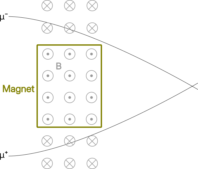
Fig. 3: A schematic, simplified visualization of the return field problem of a single dipole magnet. The return field of the dipole magnet could deflect the muons back into the detector.
Therefore, a single dipole magnet is not suitable to deflect the muons away from the detector. A more complex system of multiple magnets is needed.
Active Muon Shield
The "Active Muon Shield" is a system of magnets to deflect the muons with energies between \(1\,\text{GeV}\) and \(350\,\text{GeV}\) away from the detector. It is the most challenging part of the SHiP experiment. Its shape has been optimized with GEANT4 simulations in combination with Bayesian optimization to minimize the number of muons reaching the decay vessel. \(\mu^+\) should be deflected to the left and \(\mu^-\) to the right.
The design approach uses multiple magnets with changing magnetic field geometry and strength in a \(20\,\text{m}\) long free-standing configuration. The first magnets spatialy separate the \(\mu^+\) and \(\mu^-\) from each other. All the following magnets deflect the muons away from the detector, while simultaneously using the return field to prevent particles from being bend back to the detector. Fig. 4 shows a schematic visualization of the active muon shield and Fig. 5 shows a CAD model of the active muon shield.
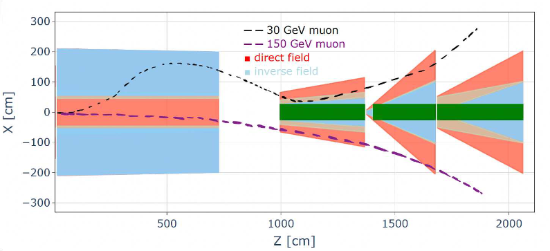
Fig. 4: A visualization of the structure of the active muon shield with the paths of two deflected muons3.

Fig. 5: A CAD model of the active muon shield4.
A simulation of the muons from the beam dump, deflected by the active muon shield, is shown in Fig. 6. The simulation shows the formation of a muon-free region (blue) around the decay vessel.
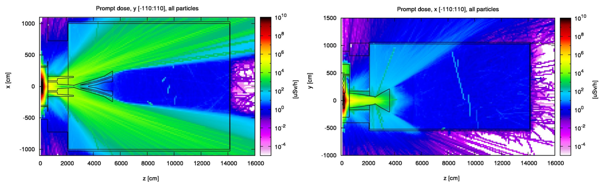
Fig. 6: A simulation of the muons shield efficiency. The left figure shows a view from the top and the right figure shows a view from the side. Blue areas indicate a low muon density5.
-
https://arxiv.org/pdf/1703.03612, Section 1 ↩↩
-
https://arxiv.org/pdf/1703.03612, Section 2 ↩
-
https://agenda.infn.it/event/43758/contributions/253051/attachments/134295/200895/SHiP_LDMA_2025.pdf, Slide 7 ↩
-
https://cds.cern.ch/record/2704147/files/SPSC-SR-263.pdf, Section 3.1 ↩
-
https://arxiv.org/pdf/1504.04956, Section 3.7 ↩